Martin Schimmel presents a case demonstrating the clinical application of the CM Loc Flex implant
A female 67-year-old patient with an edentulous upper jaw was selected for this clinical procedure. She had received four Straumann Standard Implants (SLA active surface, 8mm length, regular neck, 4.1mm diameter, Straumann, Switzerland) in March 2011.
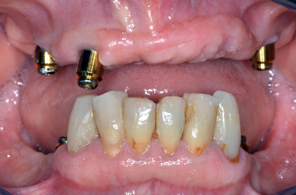
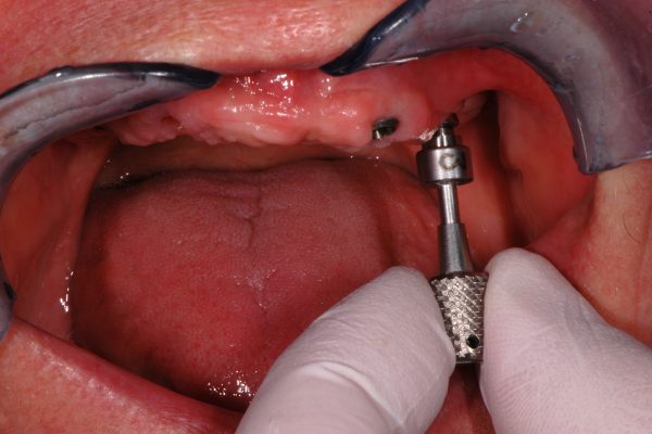
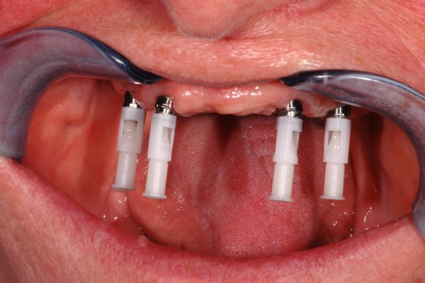
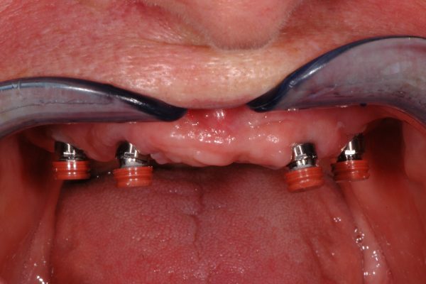
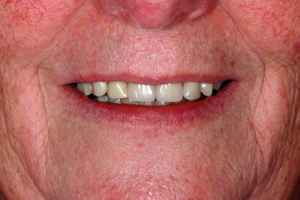
Figure 1 (main picture above): Clinical scenario with malaligned implants and Locator attachments; the implant UL2 was already lost. The attachment showed severe signs of wear and needed to be replaced
The implants has been placed following the recommended surgical protocol for edentulous patients in the maxilla without augmentation procedures, but due to insufficient local alveolar bone mass they had been placed in an unfavourable angle for the subsequent prosthetic restoration.
One implant in the region of the UL2 was lost (Figure 1) and another implant was placed in the region in September 2015. The implants were loaded using Locator attachments (Zest Anchors, USA) to retain an implant supported overdenture (IOD).
It was then decided to change the IOD retaining attachments in order to establish sound mechanical and biological conditions.
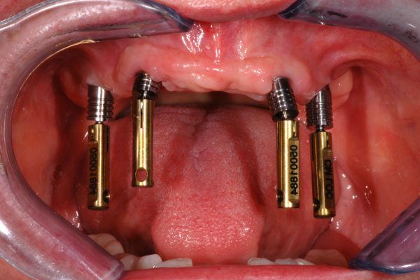
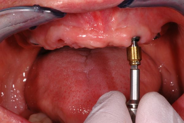
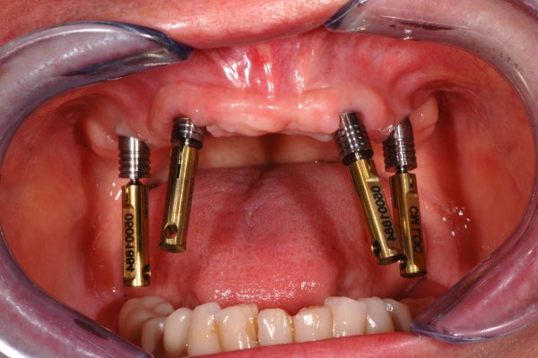
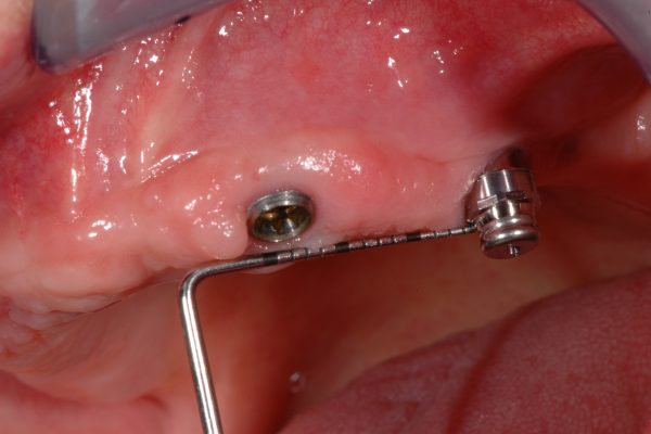
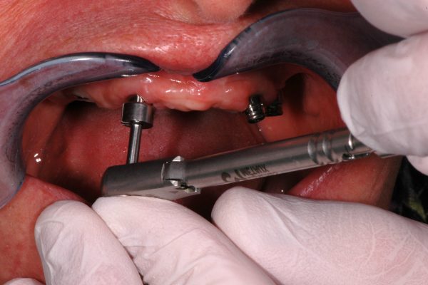
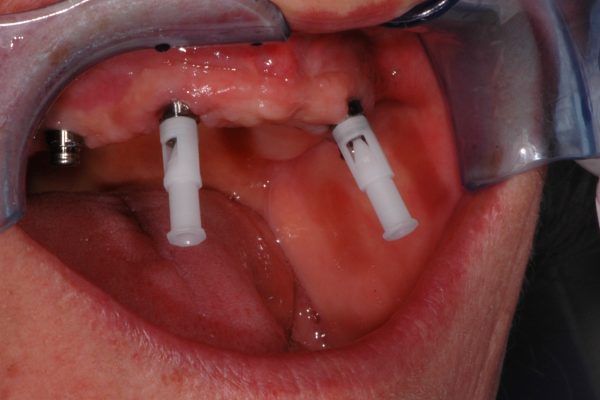
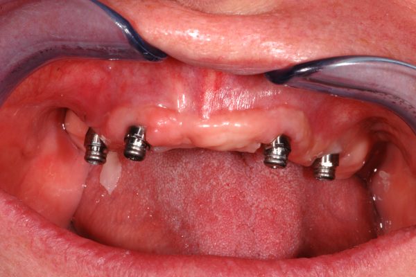
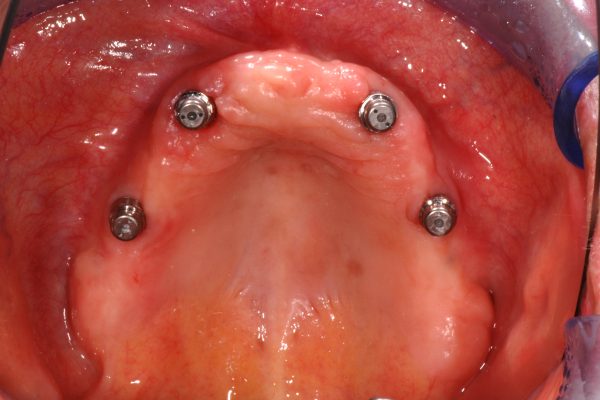
At first, the Locator attachments were removed (Figure 2) and the appropriate height of the CM Loc Flex abutments were selected (Figure 3). The converging angle between the implants was verified three-dimensionally using the CM Loc Flex case guide (Figure 4).
It became evident that the angle between the implants exceeded 10° but not more than 30°; therefore the CM Loc Flex was selected for this patient. The treatment plan aimed to arrange the abutments parallel to the occlusal plane to improve the clinical situation.
The CM Loc Flex abutments were placed carefully into the implant and screwed in by using the CM Loc Flex screw driver (Figures 5a and 5b). The final torque of 35Ncm was applied with the CM torque wrench (Figure 6).
Subsequently, the CM Loc Flex aligners were placed onto the abutments and were firmly moved on to the fixed position, which is clinically well defined and within the axis of the implant (Figure 7). It clicks when reaching the intended position.
It was planned to first align the two central abutments and to align the remaining abutments in a second step, as the capsules of the employed cement contain only enough cement for two abutments.
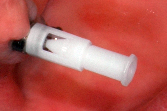
The correct seating of the aligners was controlled by verifying that the aligner’s filling funnel was properly seated in the central filling hole of the CM Loc Flex (Figure 8).
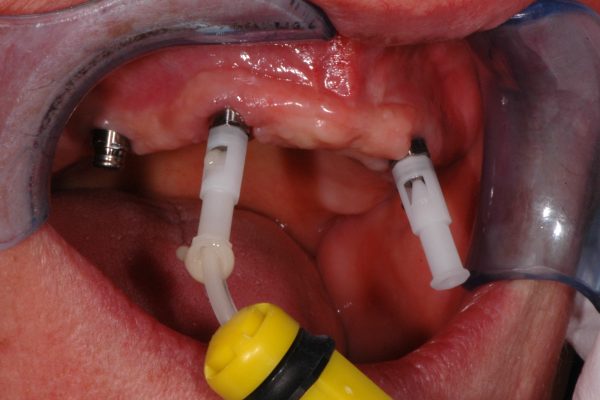
The next clinical step comprised the injection of composite bonding cement. In this case, Relyx Unicem self-adhesive universal resin cement (3M ESPE) was used. The injection cannula was placed on the first aligner, the cement was injected and it was well taken care of that the cement leaked out of the two vent holes on the top of the abutment (Figure 9).
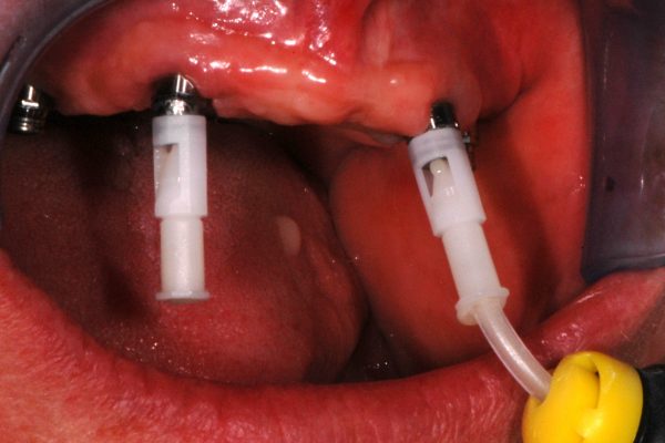
Using the same Relyx capsule, a second aligner was charged during the working time of the cement as described in the IFU (Figure 10).
During the specified working time of the 3M ESPE Relyx Unicem, the alignment of the first two abutments was performed. Therefore, the CM Loc Flex aligner was tipped into the opposite direction of the implant axis in order to find the movable position of the aligner. Subsequently, the abutments were aligned:
- Parallel to each other both in the buccal-lingual and mesial-distal planes
- Perpendicular to the occlusal plane.
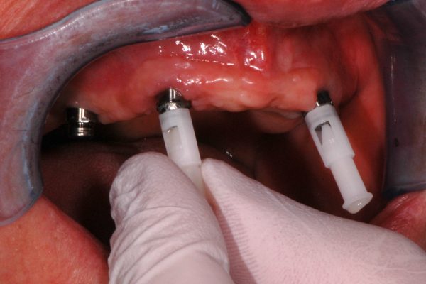
Subsequently, the remaining two CM Loc Flex aligners were filled and aligned (Figure 11).
The exact same steps were repeated to align the implants in the regions UR4 und UL4 parallel to the central aligners. The alignment of the abutments was verified in all three dimensions (Figure 12).
After allowing complete curing of the cement, the aligners were removed (Figure 13a) and the abutments cleaned (Figure 13b). The procedure was performed uneventfully; it proved to be simple and well described in the current version of the IFU.
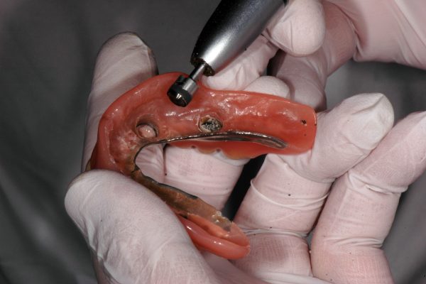
The following steps of fixing the retentive parts into the existing denture are clinically well established and do not differ to other stud-type IOD-attachment systems. The first procedure required the removal of the Locator housings from the denture, which was performed with the CM Loc housing extractor (Figure 14).
Subsequently, the CM Loc impression part were placed onto the abutments and it was verified that there was sufficient space in the denture base for them to be incorporated (Figure 15a).
As the placement of the CM Loc impression part would have required substantial removal of the metallic framework, it was decided to use the CM Loc housings with mounted CM Loc retention inserts for the relining impression (Figure 15b).
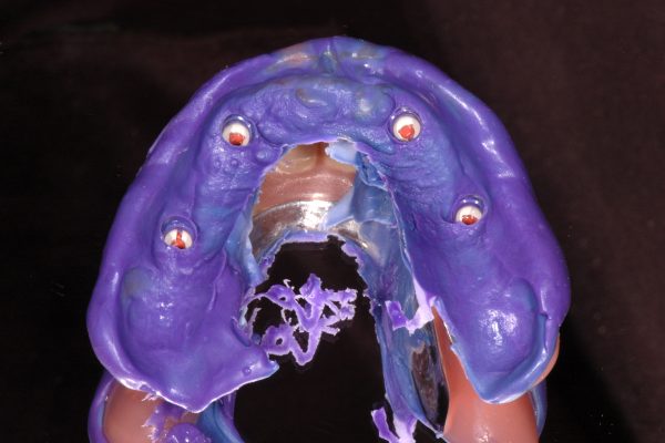
The reline impression was used employing Impregum soft polyether impression material (3M ESPE) (Figure 16).
During the setting time of the Impregum, the denture was placed into the mouth and the patient was asked to remain in central occlusion until the material was set.
The impression was disinfected and sent to a dental laboratory for a reline and incorporation of the CM Loc Pekkton housings.
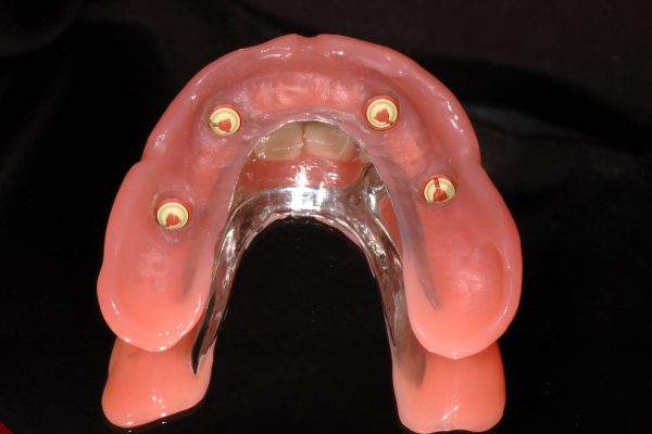
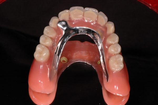
The IOD retained with CM Loc Flex abutments and housings with extra-low retention force inserts was delivered on the same day (Figures 17 and 18).
Applicability of the IFU (version 11.2015)
In the first part of the current documentation, the feasibility of the clinical steps as described in the IFU for the CM Loc Flex abutment was demonstrated. This description refers, among others, to the chairside alignment of the attachment and lab-based fixation of the housing in the denture base, which is (from a clinician’s point of view) the technically most demanding procedure.
The IFU defines very well the criteria for selecting the CM Loc Flex, thus the three-dimensional orientation of the supporting implants. The CM Loc Flex abutment offers the clinician and the supporting dental technician a very wide spectrum of
clinical applications.
Conclusion
The current IFU describes the clinical and technical procedures for the CM Loc Flex abutment of Cendres+Métaux SA. The IFU allowed me to apply the described procedures from first use after reading the IFU attentively. No deviation from the described procedures was necessary in order to achieve a highly satisfying clinical result.
Disclaimer
The patient provided informed written consent to publish her pictures. The surgical treatment was paid for by the patient. Martin Schimmel and Patrick Zimmermann have no direct or indirect financial relationship with Cendres+Métaux SA and did not receive benefit in kind or cash for the current report.
The current case report was part of an agreement between the Division of Gerodontology (University of Bern) and Cendres+Métaux SA for the documentation of five clinical cases with the CM Loc attachment systems. Cendres+Métaux SA provided the parts and indemnified the Division of Gerodontology and the dental laboratory (Zahnmanufaktur).

